Caster loss ≈ loss-per-inch × lift (IFS ≈ 0.5°/in, solid axle ≈ 1.0°/in)
New caster = stock caster − caster loss
Half-shaft / CV angle = arctan(lift ÷ control-arm length)
U-joint limits are speed-dependent (Spicer): ≈3° vibration-free (max-life guideline), ≈4.2° @ 4,000 RPM, ≈11.5° @ 1,500 RPM
Lifting your truck or SUV changes more than just ground clearance. When you add suspension lift, whether through a leveling kit, spacer, or full lift kit, you alter the geometry of every moving component in your front suspension. Two of the most critical effects are caster angle change and increased CV/U-joint operating angle. Ignore either one and you will pay for it in premature part wear, handling problems, or outright joint failure on the trail.
Caster angle is the forward or backward tilt of the steering axis as viewed from the side. Positive caster (top of the steering axis tilted toward the rear of the vehicle) provides straight-line stability and self-centering steering feel. Factory engineers tune caster carefully: most modern trucks and SUVs run 3–7° of positive caster. When you add a suspension lift, the lower control arm drops relative to the frame, and the geometry that created that positive caster is disrupted. The result is reduced positive caster, sometimes going negative in severe lifts. The driver experiences this as wandering at highway speeds, a need to constantly correct steering, and a "loose" front end feel.
CV (constant velocity) and U-joints convert rotational power from the differential to the wheel while allowing the suspension to travel. Both joint types have angular limits, but those limits are speed-dependent, not a single cutoff. For U-joint driveshafts specifically, Spicer's published guidance is roughly 3° for vibration-free, maximum-life operation, about 4.2° at 4,000 RPM, and as much as 11.5° at 1,500 RPM — the faster the shaft spins, the less angle it tolerates. Those U-joint figures don't carry over to CV joints: CV-joint (common on IFS half-shafts) tolerable angle is joint- and vehicle-specific, set by the boot and joint design, so check that CV joint's own manufacturer rating rather than applying Spicer's U-joint numbers to it. The static geometric angle this calculator estimates is also not the same thing as true operating angle: true operating angle is the difference between the slopes of the two connected components (for example, the differential output shaft versus the half-shaft), which requires a direct measurement, not just a lift-height calculation. Treat any lift as a prompt to measure actual angles and check them against your U-joint or CV-joint manufacturer's speed-rated limits before assuming geometry alone tells you enough.
For IFS vehicles, a suspension lift raises the body relative to the differential, which sits lower in the frame and cannot move. The half-shaft, which runs from the differential to the wheel, must now operate at a steeper angle. A 3-inch lift on a vehicle with 14-inch half-shafts creates roughly a 12° static CV angle; a 6-inch lift on the same vehicle pushes past 23°. There is no single number where this becomes unsafe — it depends on driveshaft speed and the true operating angle between components — but larger static angles leave less margin, so measure before you drive on it.
The two main correction strategies differ in both cost and completeness. Caster correction shims are angled wedges that tilt the axle or strut to restore positive caster angle. They are inexpensive and easy to install. However, they do not change the length or pivot geometry of the control arms, so they do not address the CV angle problem. For solid axle vehicles on smaller lifts, shims are often adequate. For IFS vehicles on moderate to large lifts, shims are a partial fix at best.
Extended upper control arms (UCAs) are the geometrically correct solution for IFS vehicles. By moving the upper ball joint outward and often upward, UCAs restore the factory suspension geometry at the new ride height. This simultaneously corrects caster angle and reduces the CV operating angle, addressing both problems with one part. Quality UCAs from companies like SPC, Camburg, or Icon use longer arms with improved ball joints and are engineered for specific vehicle platforms. They cost more than shims but are the only way to properly sort the geometry on a seriously lifted IFS truck.
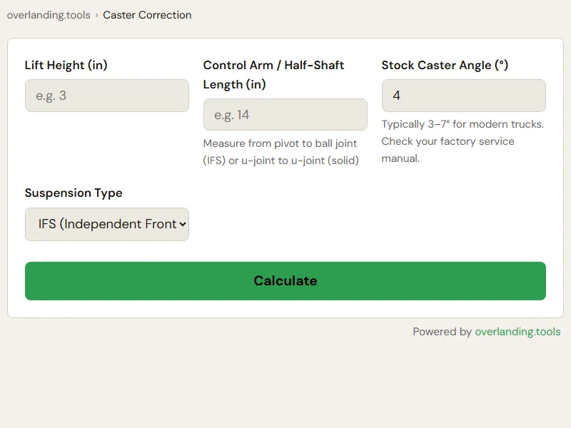
Use this calculator as a first-pass check. Enter your lift height, half-shaft or control arm length, stock caster angle, and suspension type. The calculator estimates the static half-shaft/driveshaft slope from that geometry — not a measured operating angle — and gives a rough rule-of-thumb estimate of caster change (roughly 0.5° per inch of lift for IFS, ~1° per inch for solid axles). Actual caster loss depends on your specific caster/radius-arm geometry and should be confirmed on an alignment rack. The CV/half-shaft angle is a static geometric estimate only — measure your actual operating angle and check it against your U-joint or CV-joint manufacturer's speed-rated limits before deciding whether extended UCAs or other fixes are needed.